
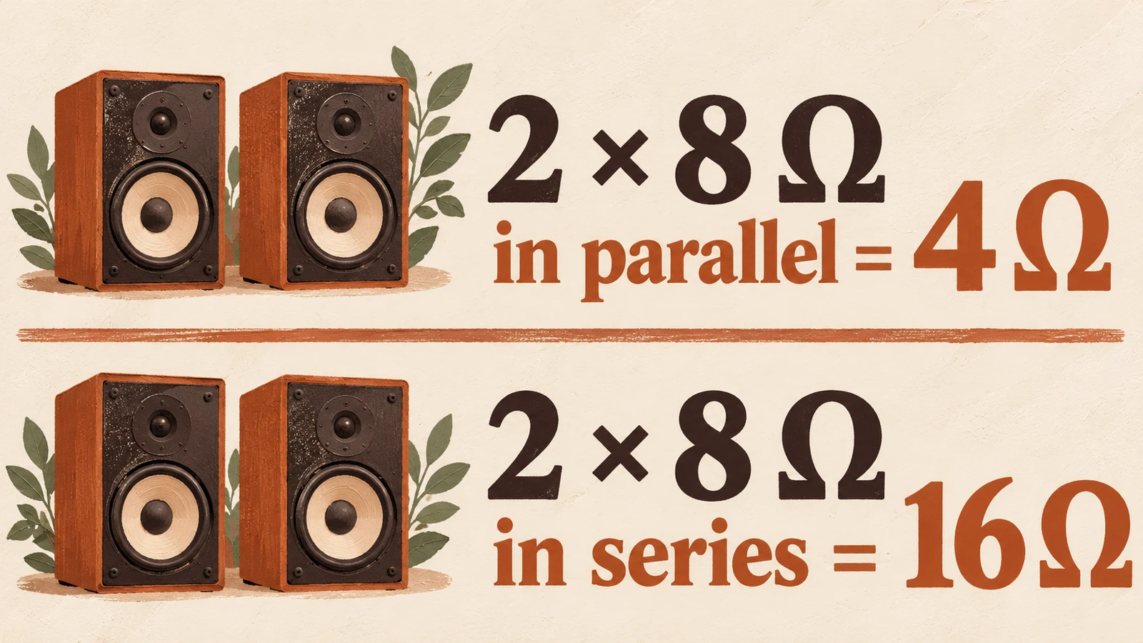
Short answer: Speaker impedance describes the electrical load presented to an amplifier, expressed in ohms. Adding conventional passive speakers in parallel lowers the combined nominal load: for example, two equal eight-ohm speakers make a four-ohm load. Yamaha's speaker guide illustrates that calculation and explains why the amplifier's supported load matters.
Before adding a speaker in a cafe, shop or reception area, identify the amplifier channel, every connected speaker and the wiring arrangement. Then compare the combined load with the actual amplifier manual for its selected operating mode. A louder room is not a reason to skip that check.
Calculate the load on each channel, not across the building
The relevant load belongs to the amplifier output driving that speaker circuit. Keep the left and right channels separate in your record, and check any other configured outputs individually. Do not average the speakers across the venue or assume that spare capacity on another channel makes an unsuitable load acceptable. The equipment manual determines the permitted arrangement.
For equal conventional speakers connected in parallel, divide one speaker's nominal impedance by the number on that channel. Yamaha's parallel-speaker examples show the principle. These calculations describe nominal loads; they are not approval to connect a particular amplifier or a replacement for its installation instructions.
| Example on one channel | Nominal calculation | Result |
|---|---|---|
| Two eight-ohm speakers, parallel | Eight divided by two | Four ohms; parallel-load principle |
| Four eight-ohm speakers, parallel | Eight divided by four | Two ohms; calculated using the same parallel-load principle |
| Two four-ohm speakers, parallel | Four divided by two | Two ohms; Yamaha example |
The next question is whether the amplifier supports that load in that mode. If the manual does not permit it, stop and have the circuit designed correctly. Do not treat a protection circuit as permission to try an unsupported connection.
Parallel and series describe different wiring arrangements
Parallel wiring connects branches across the same output; series wiring places loads along a shared path. Their nominal arithmetic differs. Series impedances add, while parallel loads combine through their reciprocals. That distinction explains why adding a cabinet does not always mean adding its stated impedance to the total. Identify the wiring before calculating the result.
For an unequal parallel pair, use the product divided by the sum of the nominal impedances. An eight-ohm and a four-ohm pair gives thirty-two divided by twelve, or approximately two point six seven ohms. This is a calculated nominal example using the parallel-load method, not a recommendation to use that load.
For a series pair of eight-ohm speakers, the nominal sum is sixteen ohms, as recorded in the calculation examples. Do not rewire installed speakers in series simply to make the arithmetic look acceptable. Ask the installer to assess the speakers, crossover behaviour, power distribution and required performance as a complete design.
Daisy-chaining does not automatically mean series wiring
A cable running from one cabinet to the next can look like a chain while the electrical connection is parallel. Read the cabinet's connector diagram. Yamaha's guide describes passive cabinets whose paired connectors are used to pass the amplifier's signal to another speaker. The physical route of the cable alone does not establish the circuit.
This is a common reason to check the installed equipment before ordering “just another matching speaker.” The additional connector may be convenient, but the resulting channel load still needs calculation. Label both the amplifier end and the speakers so a later maintenance visit does not have to reconstruct the arrangement from appearance.
Keep a photograph of the labels, a simple circuit record and the relevant manual pages. If an existing connection cannot be identified confidently, have it traced with the system safely isolated by a competent person. Guessing from cable colour or the shape of a socket can produce the wrong starting assumption.
A parallel-mode switch is a separate question
Do not infer the speaker load or output wiring from a switch labelled “parallel.” An amplifier's operating-mode control can describe how its inputs feed channels; its meaning and output requirements depend on that model. Read the mode diagram and permitted-load table together. Do not bridge outputs, join output terminals or change the mode based on a generic internet diagram.
For a venue record, write the amplifier model, selected mode, channel and connected circuit on the same line. That makes it possible for an installer to check the actual arrangement instead of receiving only the speaker count. Include any change made during an event or equipment replacement so the next shift is not relying on an outdated drawing.
The active versus passive speaker guide helps identify where amplification sits. These passive-load calculations are not the method for linking the line-level inputs of powered speakers. Establish which type of system you have before applying a formula.
Nominal impedance is a starting specification
Treat the nominal rating as a system-matching specification, not a promise that a speaker presents the same electrical load in every condition. Check the amplifier manufacturer's compatibility guidance for the intended speakers and mode. A calculation can flag an obvious mismatch; it cannot establish the full electrical or acoustic behaviour of an installation.
Ask the installer what evidence they used, including the speaker and amplifier specifications, cable runs, operating mode and planned level. A resistance reading taken from a disconnected speaker is not a substitute for identifying its published impedance specification. Likewise, a system that plays briefly at a low level has not thereby passed its design checks.
If distortion or protection behaviour appears, reduce the level and investigate rather than adding more speakers or increasing gain. The amplifier clipping guide explains how to separate a source problem from a later stage of the playback chain. Impedance is one part of that investigation, not a diagnosis of every distorted sound.
Constant-voltage systems need their own design method
If the equipment is labelled for a constant-voltage distribution system, use its amplifier and speaker-tap instructions instead of applying the conventional low-impedance examples above. A tap rating and a low-impedance terminal describe different arrangements. Have the installer identify which terminals and settings are actually in use before making changes.
For the overall venue, the background-music setup guide connects equipment, coverage, operating responsibility and source choice. Use the business-type directory for the room's practical needs. An extra speaker should be a response to a defined coverage problem with a compatible design, rather than a guess about loudness.
Sonosfera supplies the music source, not amplifier design or electrical installation. Browse its catalogue and check the current UK plan when the music and catalogue terms fit your venue. Keep the equipment approval and music-service decision as separate items in the handover.